Thursday, October 29, 2009

Early stages of the ATR72 Throttle Quadrant

From photos and other pieces of information I'd collected from a wide range of sources, and with some minor adaptations to suit both my abilities and the material available, here's how it all started life ...


The throttle and condition levers are made from some aluminium extrusions I found at our suppliers, and although the dimensions are not quite true to the real aircraft, they're close enough to be used in a simulator. Most of this stuff is hidden below the top cover at a later stage and is barely seen.


The flaps lever and the gust-lock lever are made from some stainless steel tube, which was found just laying around in the workshop - or rather, awaiting its purpose. There's an inner and outer tube, which (as the outer tube has the axle pin going through the bottom) allows the inner tube to slide in and out over a short distance. Seeing as there are no great stresses put on these parts however, they could just as easily have been made from aluminium. The flap knob was carved from a piece of scrap wood that I found lying about.


The park brake lever is a flat aluminium bar and there's a spring mounted on the axle which enables the lever to be moved sideways to clear the stops (a thin strip of plywood) for releasing the brake. The parking brake has a spring return when it's released.


Inside the condition levers is an aluminium bar, and attached to this is the pin that slips into the notches along the top arc of the quadrant. You will see that it protrudes out the other side slightly, which creates an attachment point for the spring return. The longer pin which you can see protruding (near the top of the photograph) is the actual release lever for the condition knob. The small cables are for Fire Warning lamps that one day will go in the head of the conditon knobs.

The brass pin in the flaps lever (which is a tight press-fit into the inner tube) slips into the notches along the top arc of the quadrant, and has a spring return on the other side in a similar manner to the condition lever.


This is a view of the mechanism behind the gust-lock lever, showing its return spring, throttle stop bar, and the arc in which its latching pin travels and locks into at each end.


The next photo is from the lower rear and shows the notches that the various levers slip into.You can also see the return spring for the throttle reversers. The row of three small nails was a temporary stop for the flap lever, which eventually had a small wooden block glued and nailed into place.


And this is it mounted inside the throttle box ...


Wednesday, October 14, 2009

Rudder Pedals

This entry is dedicated solely to the construction process of the rudder pedals I made for the ATR simulator, and as such is a fairly detailed account. So as to illustrate where exactly it is we're headed though, I'll start at the end ... Here’s how all the individual components eventually turn out.

The next photograph shows the cross-arm which links the Captain’s rudder pedals to the F/O’s pedals.

Here's a better view of the entire push-rods and cross-arm assembly.

Here's how the main push-rod ball joint is attached.

This is the piece you put your foot into. Note the spring that gives a ‘feel’ to the brakes. You can also see the wire push-rod that operates the arm on the pot which is connected to the brake axis.

One completed assembly as viewed from the top.

And, of course, one completed assembly as viewed from underneath.

Next is an under-pedal view showing the bearing blocks and the brake axis pot with push-rod and return spring. I used acetal for the bearing blocks because it's easy to machine, dimensionally stable, and has reasonable wear properties.
DO NOT USE NYLON
– it is hygroscopic and as it absorbs water, the size of the hole will change and bind up on the shaft.

Brake axis pot from a different angle.

Followed by an even better angle of the brake mechanism.

This is another angle of the pedal bearing blocks. The collars which prevent the shaft from moving sideways in the bearing blocks is just a piece of thick walled pipe with a screw threaded into the side of it.

Bearing blocks again, and note the screw with nuts either side of the shaft . This allows for adjustments to be made with regards the angle of the pedal to the shaft when the brakes are released.

This shows the countersunk screws going through the rudder pedal to the bearing blocks. Also, you can see the bearing blocks at the bottom of the rudder arm.
I made them from acetal, and because I didn’t have any larger material on hand, I made two of them side by side to give more strength. Ideally it should be one piece.

Here's a better view of the bearings and collar.

Both completed assemblies.

The next few photos show a trial setup designed to test operation. Note the different type of rod-ends here. These were eventually found to be unsuitable because they're effectively sprung-loaded internally, which produces a sloppy action when using the rudder pedals. The round grey rod-ends in most of the previous photos are perfect for the job.

Another angle on the trial setup.

And yet another one, to better show how all the bits and pieces fit together.

The last photograph shows a trial setup in the actual simulator, with wooden blocks being employed instead of the lovely aluminium pedals which eventually replaced them. This trial was just to get a better feel for the angles and range of movement.


Another entry with regards my simulator's development will be posted next week, concerning what I'm not yet quite sure ...

Sunday, October 11, 2009

Humble beginnings ...

The following photographs show the very early stages of my ATR72 flight simulator, which is housed in a recent addition to our home garage (how convenient!). This project goes back to the early part of 2003 and, of course, has been interrupted by the unfortunate necessity of proper employment, although during the process we've actually designed several flight simulator products which are currently being sold. More information about these can be found here.

Anyway, back to where it all began ...

100mm x 50mm beams were used as a base so as to keep the floor high enough to allow for some underfloor mechanisms and cables to be placed (and hidden!) there at a later stage.

This is the first of many modules and everything is screwed together rather than nailed, just in case it has to be moved in years to come. Cockpits don't fit through standard doorways very nicely!

Here you can see the side frames taking shape and the central console holds the mounting bases for the Captain and F/O flight instrument monitors.

A pair of old car seats were employed for the Captian and F/O. It was necessary to slightly modify the front edge of each seat with a cut-out (to allow the control yoke to fit when the seat is positioned well-forward at the same time as the yoke is being pulled well-back) before they were re-upholstered.

Here you can see the initial parts of the glare shield under construction with the F/O flight instruments monitor sitting in place.

And here is a trial fitting of the control columns ...

This photograph shows temporary yokes having been fitted to the control columns. A continuous chain links both yokes together with precision. Just beyond these you can also see that a trial pair of flight instrument panel cut-outs have been fitted.

The next phase of construction will follow shortly ...


Saturday, October 10, 2009

As it stands today ...

This blog has been designed to show and record the progress of my home-built ATR72 flight simulator, from the first laying of its foundations through to its current state and shall be updated regularly as various improvements are made and additions fitted. Below are some recent photos to show how it looks at the moment.

Fully-operational AutoPilot, Radios, and Landing Gear Lever and Indicators ... Click here to see a short video of the landing gear in operation.

Fully-operational Throttle Quadrant ...

The partially-operational Overhead Panel ... Click here to view a short video of it actually working (as well as the throttle quadrant being used as per a typical engine start-up ) ...

And finally, an overall view of the cockpit as it currently stands today ...

Future updates will detail the flight simulator's construction stage by stage and the trials and tribulations thereof!

Thursday, October 1, 2009

Product development

Naturally, over the course of building the simulator, various obstacles arose and effective solutions needed to be found. As a result of this, several products specifically aimed at the home cockpit/flight simulator market have been developed by myself (and by extension, the family business) and are now available for purchase through our company's website.

Following is a list of our current products, along with a brief description. Our site contains much more in-depth information about each item, including diagrams, hardware specifications, and software configuration details. Direct links to each product can be found below.

AUTOPILOT (AP5E5D)

This USB connected unit has one 4-digit with + sign, one 5-digit and three 3-digit 7-segment LED displays to emulate the autopilot displays of a typical airliner.
5 rotary encoder inputs allow the setting of Course, Airspeed, Heading, Altitude, and Vertical Speed. 2 inputs are pre-configured for the Autopilot and Autothrottle switches. No user configuration is required.
This photo shows a typical configuration complete with the mechanical rotary encoders and the toggle switches that are supplied as part of this unit. The acrylic faceplate (with milled cut-outs and smoky grey faces for the displays) is also supplied. The dimensions of this faceplate are 390mm x 65mm x 10mm.

Click here for further details.

ENCODERS and OUTPUTS (5E8R)

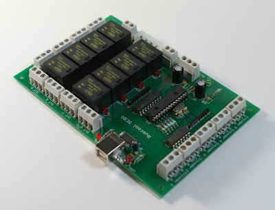
This USB connected board can accept 5 rotary encoders and 2 switches as inputs, and has 8 relays as outputs.
The supplied software allows the user to first set up the inputs and outputs as they desire in the configuration program, and then when the main program is run, all of the rotary encoders and switches will directly control Flight Simulator. The relays will respond to Flight Simulator conditions so that LEDs, Lamps, Solenoids, etc can be turned on and off appropriately. Instructions and full connection details are included.
Click here for further details.


64 INPUTS (64INS)

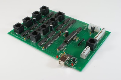
This USB connected board can accept 64 switch inputs. The supplied software allows the user to configure the inputs and then, when the main program is run, all of the switches will directly control actions within Flight Simulator. The switches are arranged in blocks of 8 utilising readily available RJ45 plugs and cables. Instructions with full connection details are included. The inputs are designed for pushbuttons and toggle switches (or any combination thereof), and even multi-position switches. They are not suitable for rotary encoders.
Click here for further details.

64 OUTPUTS (64OUTS)

This USB connected board has 64 outputs which respond to Flight Simulator parameters. A comprehensive but simple to use configuration program allows an output to be controlled from virtually any FSUIPC offset value. Each output can control LEDs, Lamps, Relays, Solenoids, etc.
Click here for further details.

DUAL RADIOS (DR5E)

This USB connected unit has two 5-digit 7segment LED displays to enable a wide range of radio configurations. Com1&2 and Standby, Nav1&2 and Standby, ADF1&2, and Transponder are available. Active/Standby with Transfer Button is configurable also. 5 Rotary Encoder inputs allow four to be used with the radios, and the fifth to be used with any other applicable function (e.g. for setting the QNH). A comprehensive but simple to use configuration program is supplied.
Click here for further details.

COCKPIT INTERCOM (RAI-2)

A full implementation of this intercom allows the Pilot and First Officer to communicate with each other, and also with an Instructor. A sidetone volume control on the board allows for the setting of how loud you hear yourself speak. The unit will accept an Electret or a Dynamic microphone and with stereo headphones, will accept stereo input from the PC so that you can hear engine sounds with more realism because sounds are heard coming from the correct direction. (The intercom can be supplied in a mono configuration if desired.) Inputs allow a Push To Talk button to be used, or a toggle switch will allow an open microphone configuration.
Click here for further information.