This entry is dedicated solely to the construction process of the rudder pedals I made for the ATR simulator, and as such is a fairly detailed account. So as to illustrate where exactly it is we're headed though, I'll start at the end ... Here’s how all the individual components eventually turn out.
 The next photograph shows the cross-arm which links the Captain’s rudder pedals to the F/O’s pedals.
 Here's a better view of the entire push-rods and cross-arm assembly.
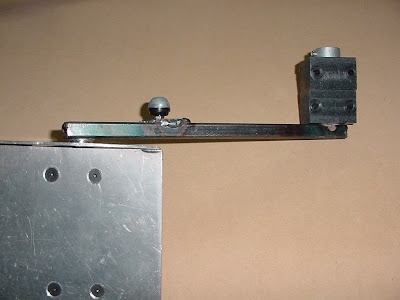
 Here's how the main push-rod ball joint is attached.
 This is the piece you put your foot into. Note the spring that gives a ‘feel’ to the brakes. You can also see the wire push-rod that operates the arm on the pot which is connected to the brake axis.
 One completed assembly as viewed from the top.
 And, of course, one completed assembly as viewed from underneath.
 Next is an under-pedal view showing the bearing blocks and the brake axis pot with push-rod and return spring. I used acetal for the bearing blocks because it's easy to machine, dimensionally stable, and has reasonable wear properties.
DO NOT USE NYLON – it is hygroscopic and as it absorbs water, the size of the hole will change and bind up on the shaft.
 Brake axis pot from a different angle.
 Followed by an even better angle of the brake mechanism.
 This is another angle of the pedal bearing blocks. The collars which prevent the shaft from moving sideways in the bearing blocks is just a piece of thick walled pipe with a screw threaded into the side of it.
 Bearing blocks again, and note the screw with nuts either side of the shaft . This allows for adjustments to be made with regards the angle of the pedal to the shaft when the brakes are released.
 This shows the countersunk screws going through the rudder pedal to the bearing blocks. Also, you can see the bearing blocks at the bottom of the rudder arm.
I made them from acetal, and because I didn’t have any larger material on hand, I made two of them side by side to give more strength. Ideally it should be one piece.
 Here's a better view of the bearings and collar.
 Both completed assemblies.
 The next few photos show a trial setup designed to test operation. Note the different type of rod-ends here. These were eventually found to be unsuitable because they're effectively sprung-loaded internally, which produces a sloppy action when using the rudder pedals. The round grey rod-ends in most of the previous photos are perfect for the job.
 Another angle on the trial setup.
 And yet another one, to better show how all the bits and pieces fit together.
 The last photograph shows a trial setup in the actual simulator, with wooden blocks being employed instead of the lovely aluminium pedals which eventually replaced them. This trial was just to get a better feel for the angles and range of movement.

Another entry with regards my simulator's development will be posted next week, concerning what I'm not yet quite sure ...
 The next photograph shows the cross-arm which links the Captain’s rudder pedals to the F/O’s pedals.
 Here's a better view of the entire push-rods and cross-arm assembly.
 Here's how the main push-rod ball joint is attached.
 This is the piece you put your foot into. Note the spring that gives a ‘feel’ to the brakes. You can also see the wire push-rod that operates the arm on the pot which is connected to the brake axis.
 One completed assembly as viewed from the top.
 And, of course, one completed assembly as viewed from underneath.
 Next is an under-pedal view showing the bearing blocks and the brake axis pot with push-rod and return spring. I used acetal for the bearing blocks because it's easy to machine, dimensionally stable, and has reasonable wear properties.
 DO NOT USE NYLON – it is hygroscopic and as it absorbs water, the size of the hole will change and bind up on the shaft.
 Brake axis pot from a different angle.
 Followed by an even better angle of the brake mechanism.
 This is another angle of the pedal bearing blocks. The collars which prevent the shaft from moving sideways in the bearing blocks is just a piece of thick walled pipe with a screw threaded into the side of it.
 Bearing blocks again, and note the screw with nuts either side of the shaft . This allows for adjustments to be made with regards the angle of the pedal to the shaft when the brakes are released.
 This shows the countersunk screws going through the rudder pedal to the bearing blocks. Also, you can see the bearing blocks at the bottom of the rudder arm.
I made them from acetal, and because I didn’t have any larger material on hand, I made two of them side by side to give more strength. Ideally it should be one piece.
 Here's a better view of the bearings and collar.
 Both completed assemblies.
 The next few photos show a trial setup designed to test operation. Note the different type of rod-ends here. These were eventually found to be unsuitable because they're effectively sprung-loaded internally, which produces a sloppy action when using the rudder pedals. The round grey rod-ends in most of the previous photos are perfect for the job.
 Another angle on the trial setup.
 And yet another one, to better show how all the bits and pieces fit together.
 The last photograph shows a trial setup in the actual simulator, with wooden blocks being employed instead of the lovely aluminium pedals which eventually replaced them. This trial was just to get a better feel for the angles and range of movement.
Another entry with regards my simulator's development will be posted next week, concerning what I'm not yet quite sure ...

No comments:
Post a Comment